Electric Gate Restoration
This project was started in April 2022 and the objective of this project was to restore an exterior electric gate that had not worked for over 15 years.
Table of contents
[[TOC]]
Context
In my backyard, there has always been an electric gate that I have rarely, if ever, seen work.
I decided to fix it because I thought I had the DIY and electronic skills to make it work again.
This gate gives access to different houses and therefore its access is shared. This implies that its operation should be low, easy and unencumbered.
It has not worked for about fifteen years since it requires a 230V three-phase power supply. The subscription was cancelled to have only single-phase and the gate remained open since that day.
Before anything
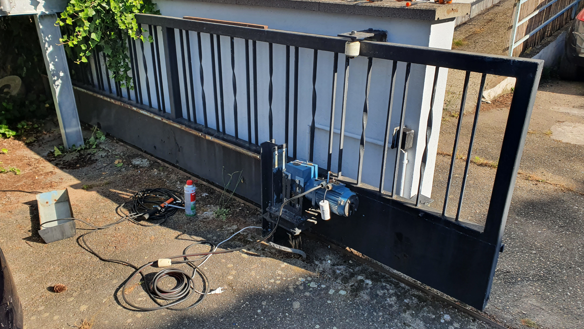
The state of the portal before starting my project was as follows:
- A three-phase motor that needs to run on single-phase (conversion required).
- Mechanical limit switches to be changed
- A broken photoelectric sensor to be changed
- The electronics of the gate to be completely redone
Required elements
Hardware
For this project, I made an electronic board to build a reliable, clean and easy to install system: LiHoCo Yard gate PCB v1.0
I also needed other components such as:
- Mechanical limit switches
- Photoelectric sensor
- Warning light
- 433MHz RF remote control
- 25µF 450V Condensator
- Junction box
- Cable
Software
ESPhome was the easiest solution to implement the portal system. I used it to make my ESP32 program
Here is the program : electric-gate.yaml
Developpement
Step 1: Check of the working existing components
The engine was the first element I tested to verify the feasibility of the project. After a little research to make a three-phase asynchronous motor work on an alternating current, I was able to verify that it turned correctly. I made the conversion from three phase to single phase using a capacitor of 25µF 450V. connected between 2 motor coils:
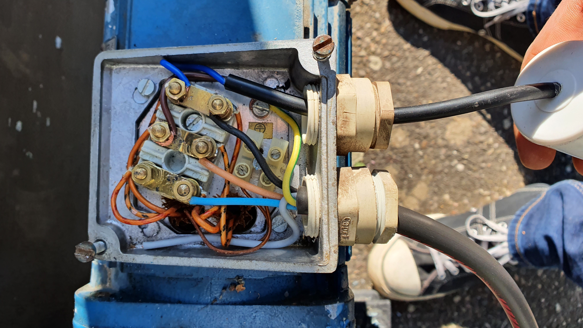 I also changed the oil of the 45/1 gearbox.
All the rest was not in working order anymore but it doesn't matter.
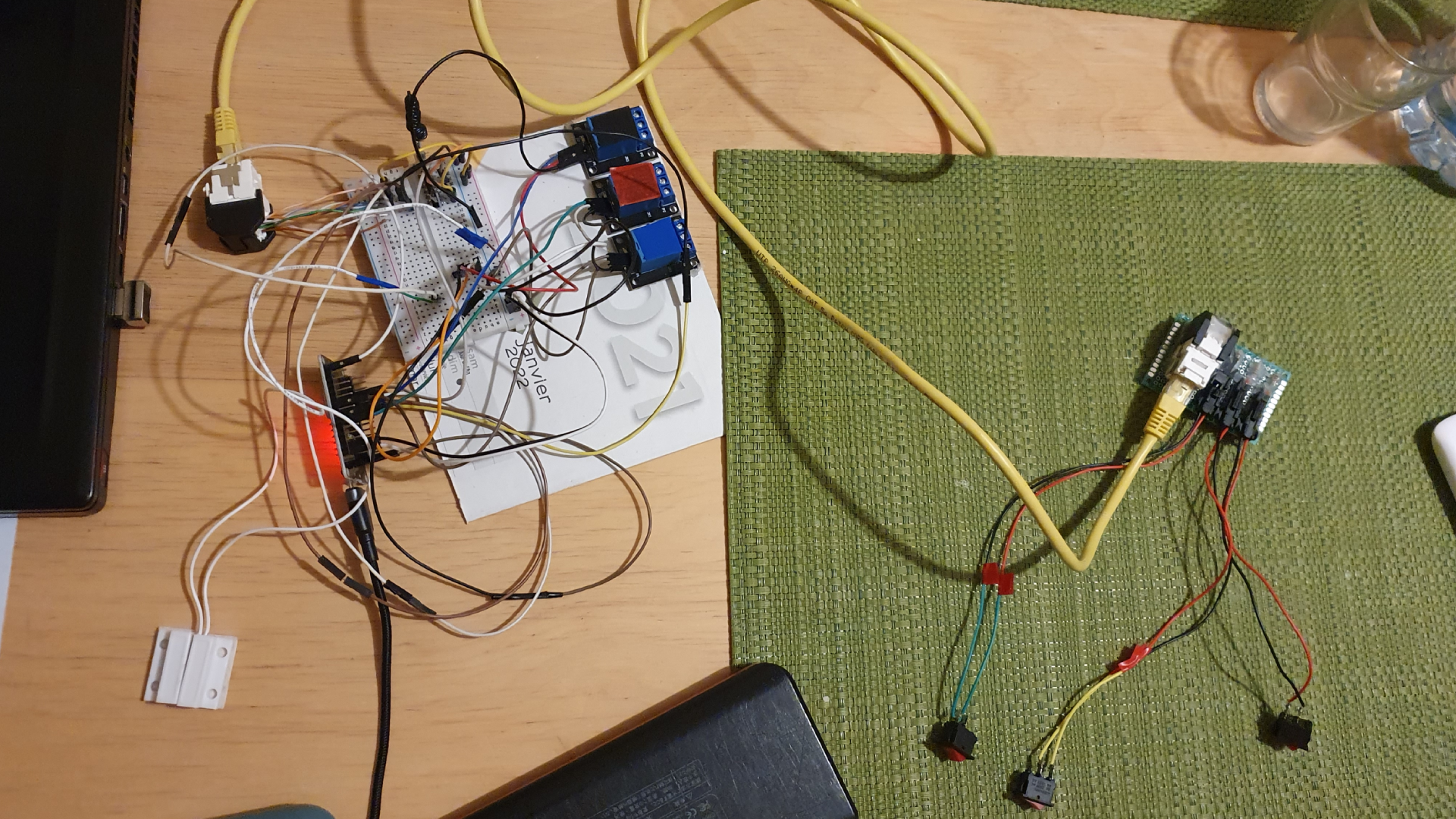
Step 2: Make a prototype circuit
The goal was to make a circuit quickly to develop the program with ESPhome and check if everything works as I wanted.
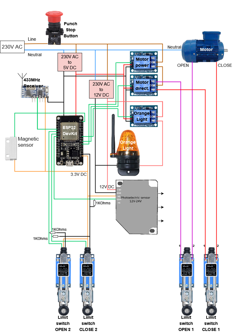
Step 3: Make a real life test
The aim now was to install the main components (limit switch, photoelectric sensor, etc...) and connect them as shown in the circuit above.
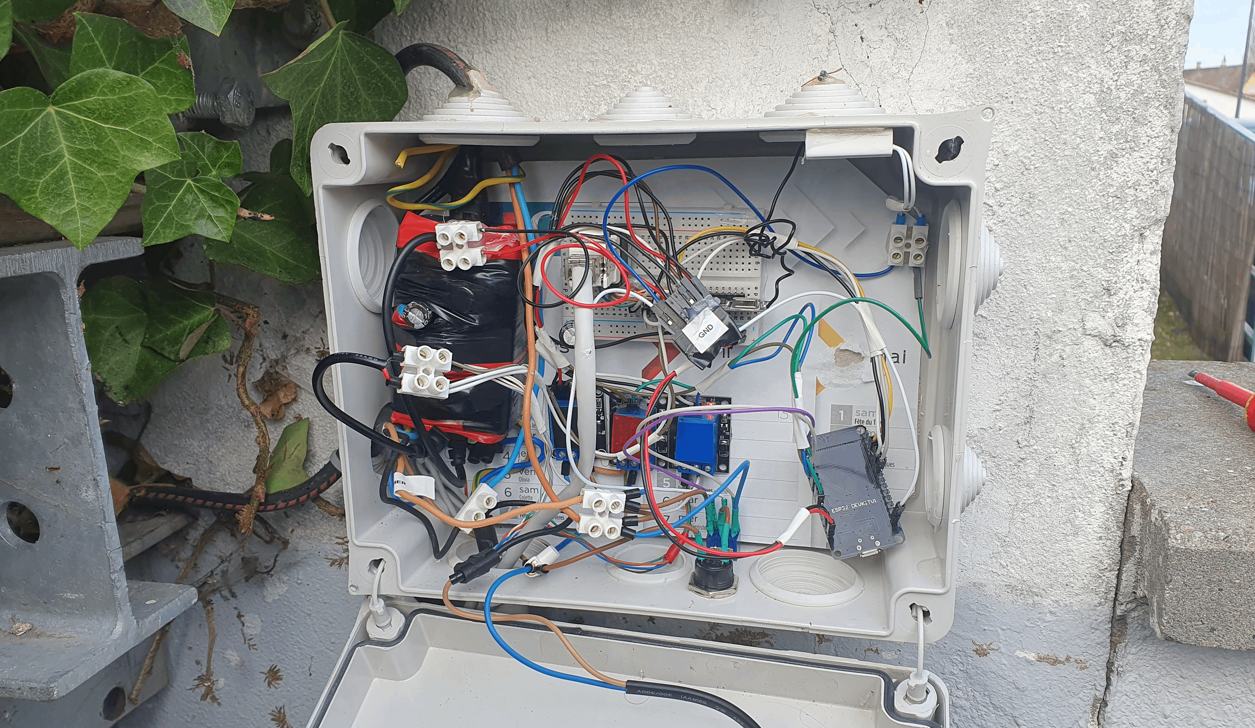
I let this prototype run for several months to see what needed to be improved, modified or removed, both physically and in the program.
I became aware of various problems:
- The sun made the photoelectric sensor think that an object was in the way, dazzling it and preventing it from closing. I installed a cover to prevent this.
- The wifi signal was difficult to pick up, either due to distance or interference. I soldered on a new antenna to avoid this problem.
- I soldered an antenna of a more suitable size for receiving the 433MHz signal, so that I could pick up the remote control signal further away (before: 10m, after: 40m).
- ...
For the program I was able to make and to optimize a few things:
- When the gate is in motion (opening or closing) and an element triggers the photoelectric sensor, it stops only if it was in the process of closing, and then reopens. Originally, the gate only stopped in the middle, regardless of movement.
- A short delay was introduced to first provide a warning light and then activate gate movement.
- ...
Step 4: Design, manufacture and installation of a new PCB
After correcting the main problems with the circuit and electronics in general, I set about designing an electrical board to make the portal's operation more reliable and, above all, more professional.
You can have a look at the PCB documentation: LiHoCo Yard gate PCB v1.0
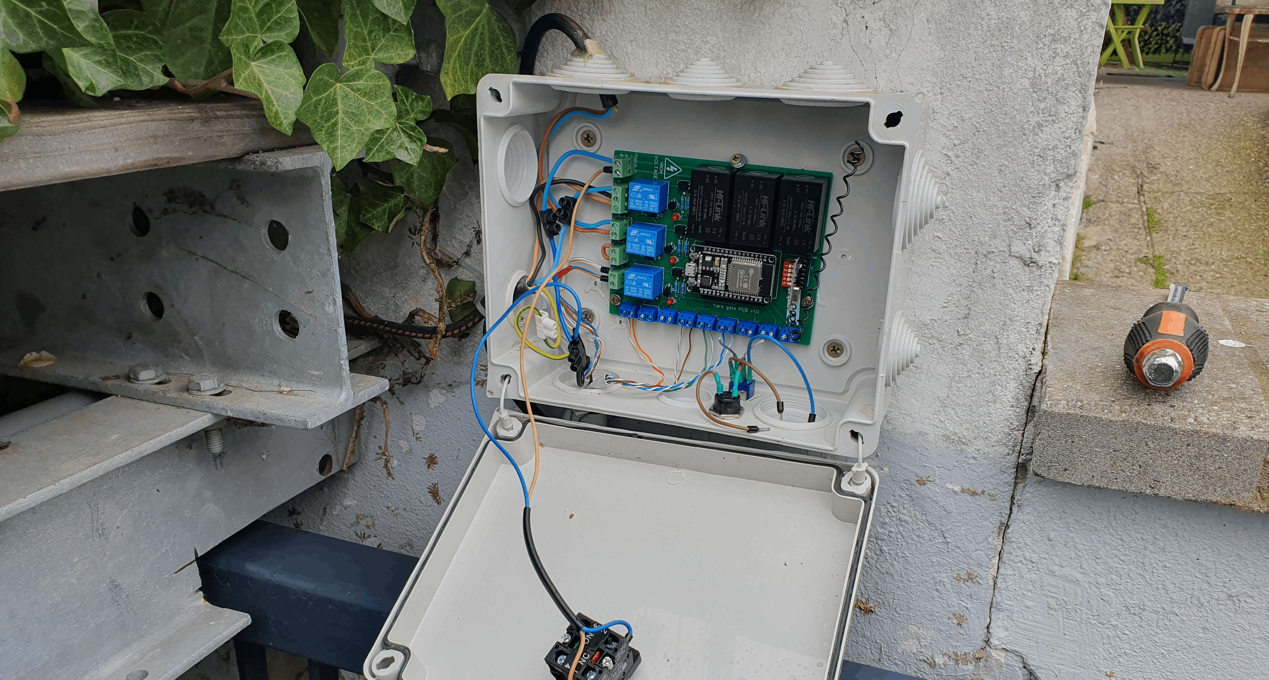
Once the electronic board was soldered and functional, I removed the prototype and installed the new PCB :
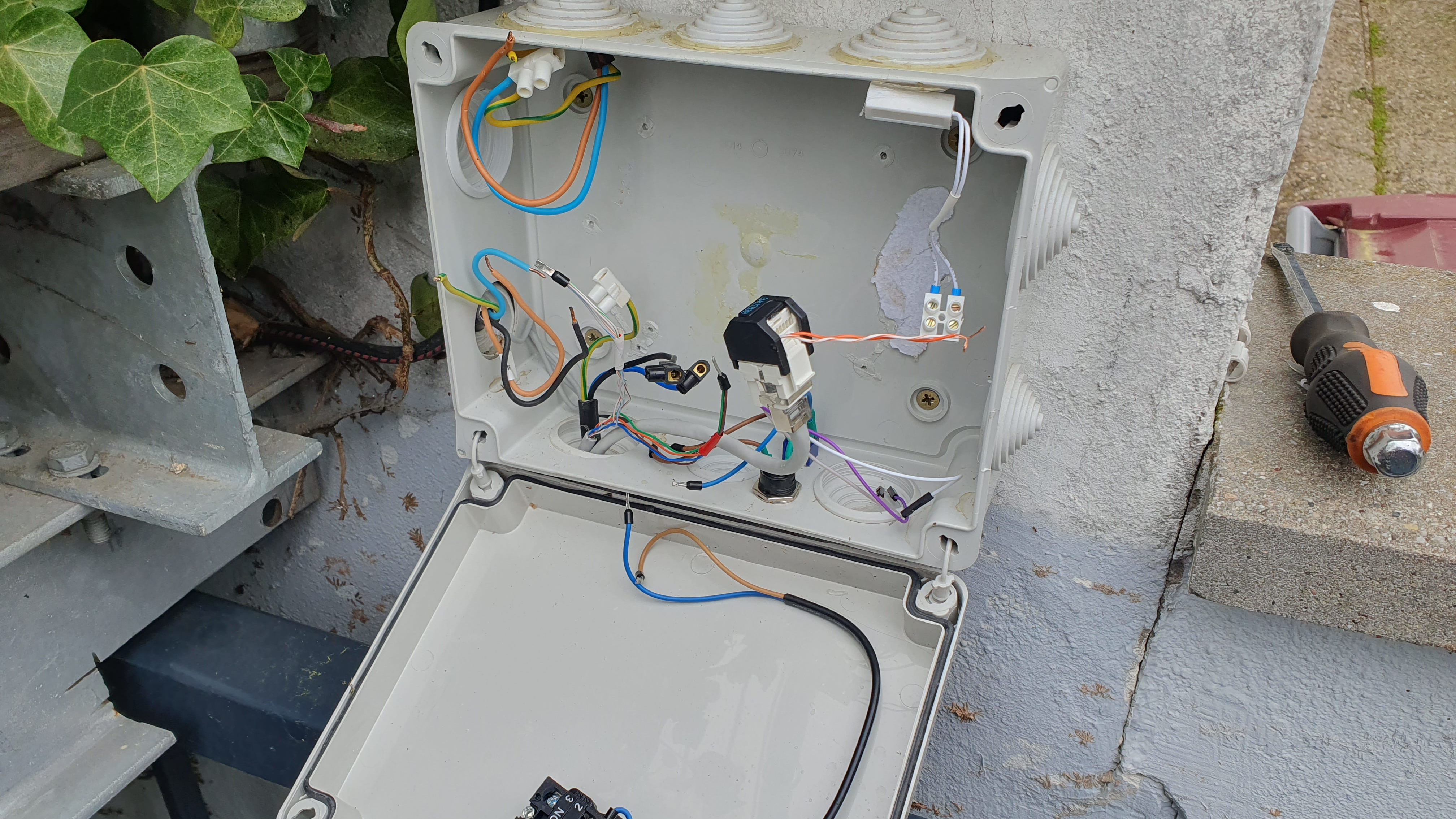
Then I installed the new PCB and here it is! #BrandNew
Maintenance
As far as gate maintenance is concerned, I had a lot of problems to solve when the prototype was installed. I'd never restored an electric gate before, nor even designed a system of this kind. So this was a first, and I was able to make a lot of mistakes in the original design, both physically and in the program. I was therefore often called upon by the gate to repair it, improve it and make it work optimally.
However, since installing the new PCB (at the time of writing, it's already been 2 months), I haven't had to make any changes to the portal. It hasn't broken down since, and I'm very happy about that.
Points of improvement
Security : No rolling code
The EV1527 433MHz receiver module does not allow code rolling as the HCS301 KeeLoq protocols do. Nevertheless, since the gate does not give any access to the interior of a house, this point does not really pose a problem.
Conclusion
In conclusion, the electric gate restoration project was launched in April 2022 with the aim of seeing it functional again after more than 15 years. The gate gave access to several houses, so it was essential to ensure that its operation was easy and hassle-free. The gate was no longer functioning since the power supply had been replaced by a single-phase supply.
The project began by assessing the condition of the gate, which included a three-phase motor to be converted to single-phase, mechanical limit switches and a broken photoelectric sensor to be replaced, as well as the need to completely overhaul the gate's electronics. The project also involved developing a reliable, easy-to-install electronic board, called LiHoCo Yard gate PCB v1.0, as well as other components such as mechanical limit switches, a photoelectric sensor, a warning light, a 433MHz RF remote control and a 25µF 450V capacitor.
On the software side, ESPhome was chosen as the solution for implementing the gate system. The program, electric-gate.yaml, was developed with ESPhome for the ESP32.
The development process involved several stages. Firstly, the feasibility of the project was tested by converting the three-phase motor into a single-phase motor using a 25µF 450V capacitor. The motor was checked for correct operation, and the gearbox oil was also changed. Other non-functional components were not a problem at this stage.
A prototype circuit was then created to quickly develop and test the program with ESPhome. This enabled further improvements and modifications to be identified. The main components, such as the limit switches and photoelectric sensor, were installed and connected in accordance with the circuit design. This prototype was monitored over several months to identify and resolve any problems.
Based on the lessons learned from the prototype, a new electrical board (LiHoCo Yard gate PCB v1.0) was designed, manufactured and installed to improve the reliability and professionalism of the gate's operation. Once the new PCB was installed, the gate was fully functional and operational.
As far as maintenance was concerned, several difficulties and mistakes were made at the outset due to a lack of experience in restoring electric gates. However, following installation of the new circuit board, no further modifications or repairs were required, and the gate has been operating optimally for two months.
One potential area for improvement is the security aspect, as the EV1527 433MHz receiver module used does not support code rolling. However, as the gate does not allow access to the inside of the houses